Contents
Index
Job Properties
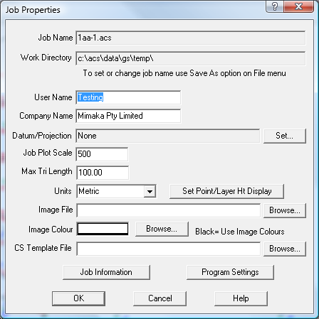
The Job Properties dialog box allows the user to set the parameters such as the working directory and plot
scale for the job.

Job Name
The job name is the file name used to save the job data on the disk.
Working Directory
This directory is generally where the .ACS file and any other input or output data file will be stored.
When a program option allows you to read or write a data file, it will be placed in this directory by default.
User Name
The username is recorded in the job for information purposes only.
Company Name
The company name is recorded in the job for information purposes only.
Datum Projections
Select a Datum and Projection from the list.
If there are none available, the configuration file may need to be set up - this is done
in Program settings
You can 'set' the datum/projection at any time, any data already in the job will not be changed.
Job Plot Scale
This scale factor is the scale at which the job is expected to be plotted. Set this at the start of the
job as it affects how the symbols are drawn. This scale factor is used with the display scale factor to scale
the size of the symbols on the screen. If in doubt use a starting scale of 1:500.
Max Triangle Length
Enter the maximum triangle length in metres. When triangles are being formed, sometimes long thin triangles
are formed down the side of the job. To avoid this, enter a maximum length. In general this should be 1.5 times
the maximum distance between field observations. If in doubt leave blank.
Units
Metric
- Distances are assumed to be in metres
- Distances will be displayed in decimal metres
- Areas are displayed in sq metres, Hectares or Sq Km
- Geodetic Datum is assumed to be in metres
- Projection units are metres
- Bearings are entered and displayed as whole circle bearings
USA
- Distances are assumed to be in decimal feet
- Distances will be displayed in decimal feet
- Areas are displayed in Acres, Roods and Perches
- Geodetic Datum is defined in metres
- Projection units (working units) are feet
- Bearings are entered and displayed as whole circle bearings
Image File
The image file can be used to provide a backdrop for the job. It is usually an aerial photo of the job.
There is an option on the zoom menu to allow the background image and the job to be ‘aligned’ so that the image
overlays the job correctly.
...
This option invokes the 'Load Image' dialog box to allow you tpo specify th image to be used.
Set Point/Layer Height Display
Click this option to set the number of decimals places for all points and layers to a certain value.
Click here for more information.
CS Template File
This file contains the templates to be used for cross section design
Job Information
This option contains additional administrative information about the job. This information can be plotted to
the plan forms if required. Click here for more information.
Program Settings
This option allows program specific setting to be altered. Click here for more information.
